HVAC
Airside HVAC
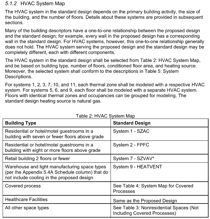
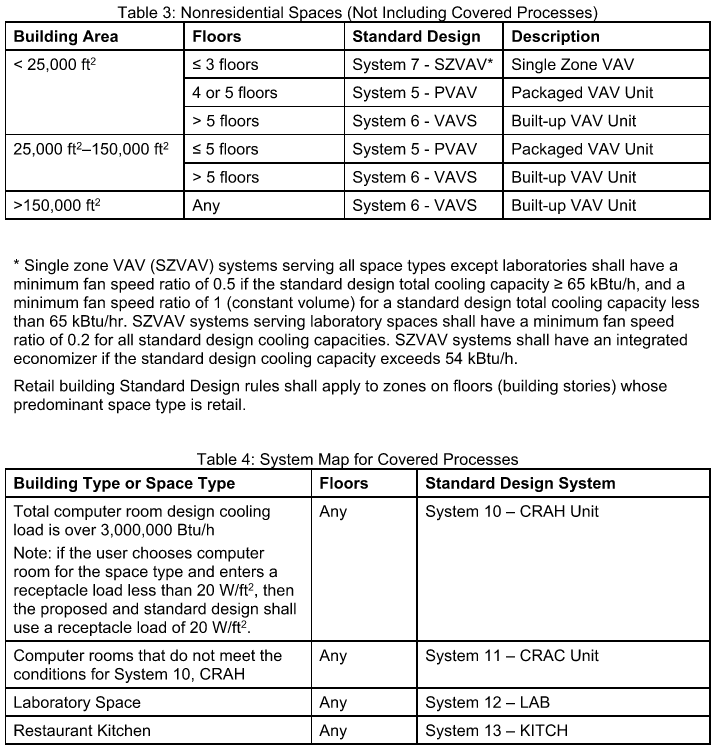
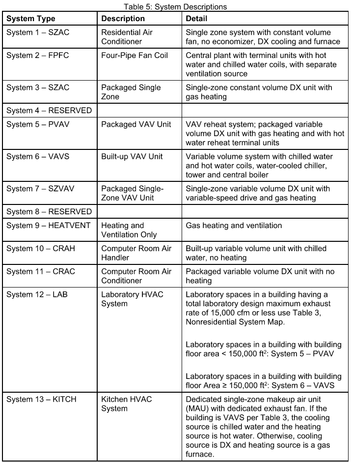
Airside HVAC system types are specified according to the HVAC System Map in the ACM Reference Manual (Table 2, below). The HVAC System map prescribes standard design system types based on the building type, building area, and number of floors. Other components of the building can also influence the HVAC type and/or required controls, including cooling capacity (e.g. economizers), occupant density (e.g. demand-controlled ventilation), and space type (e.g. kitchen, data centers, and labs). Equipment performance represents minimal compliance with the prescriptive requirements for each code vintage.
Waterside HVAC
Plant equipment is determined based on the airside system coil types and other building parameters. Airside systems with water heating coils are served by non-condensing boilers. The number of boilers serving the hot water loop is based solely on conditioned floor area, and is therefore consistent for each building type regardless of loads. Chiller type, condenser type, and quantity are dependent on the building’s peak cooling load, and therefore vary depending on climate zone and vintage.
The table below summarizes the HVAC systems serving each prototype building. Many of the prototypes are served by more than one HVAC system type, due to the variety of spaces and/or differences in thermal loads in a particular building. Chiller type and quantity are not indicated because they depend on the building’s peak cooling load, which varies by location.
HVAC Systems
| Building | HVAC System 1 | HVAC System 2 | Kitchen System | Data Center System | Lab System | Heating Plant | Cooling Plant |
|---|---|---|---|---|---|---|---|
| Asm | Sys5-PVAV | NONE | NONE | NONE | NONE | 2 Boilers | NONE |
| ECC | Sys6-VAV | NONE | Sys13 | Sys11 | NONE | 2 Boilers | Chillers |
| Epr | Sys7-SZVAV-DCV | Sys7-SZCAV | Sys13 | NONE | NONE | NONE | NONE |
| ERC | Sys7-SZCAV | NONE | NONE | NONE | NONE | NONE | NONE |
| ESe | Sys5-PVAV-DCV | Sys7-SZVAV | Sys13 | Sys11 | NONE | 2 Boilers | NONE |
| Eun | Sys6-VAV-DCV | Sys1-SZAC | Sys13 | Sys11 | NONE | 2 Boilers | Chillers |
| Fin | Sys7-SZVAV | NONE | NONE | NONE | NONE | NONE | NONE |
| Gro | Sys7-SZVAV | Sys7-SZCAV | NONE | NONE | NONE | NONE | NONE |
| Hsp | Sys6-VAV-DCV | Sys6-VAV | Sys13 | NONE | NONE | 2 Boilers | Chillers |
| Htl | Sys5-PVAV | Sys1-SZAC | Sys13 | NONE | NONE | 2 Boilers | NONE |
| Lib | Sys7-SZVAV | NONE | NONE | NONE | NONE | NONE | NONE |
| MBT | Sys6-VAV-DCV | Sys6-VAV | Sys13 | Sys11 | Sys12A | 2 Boilers | Chillers |
| MLI | Sys5-PVAV | NONE | NONE | NONE | NONE | 2 Boilers | NONE |
| Mtl | Sys5-PVAV | Sys1-SZAC | NONE | NONE | NONE | 2 Boilers | NONE |
| Nrs | Sys5-PVAV-DCV | Sys5-PVAV | Sys13 | NONE | NONE | 2 Boilers | NONE |
| OfL | Sys6-VAV | Sys6-VAV-DCV | NONE | NONE | NONE | 2 Boilers | Chillers |
| OfS | Sys7-SZCAV | NONE | NONE | NONE | NONE | NONE | NONE |
| Rel | Sys7-SZVAV | NONE | NONE | NONE | NONE | NONE | NONE |
| RFF | Sys7-SZCAV | NONE | Sys13 | NONE | NONE | NONE | NONE |
| RSD | Sys7-SZCAV | Sys5-PVAV-DCV | Sys13 | NONE | NONE | NONE | NONE |
| Rt3 | Sys5-PVAV-DCV | Sys7-SZCAV | NONE | NONE | NONE | 2 Boilers | NONE |
| RtL | Sys7-SZVAV | Sys7-SZCAV | Sys13 | NONE | NONE | NONE | NONE |
| RtS | Sys7-SZVAV | Sys7-SZCAV | NONE | NONE | NONE | NONE | NONE |
| SCn | Sys6-VAV | NONE | NONE | NONE | NONE | 2 Boilers | Chillers |
HVAC System Map & Description - ACM Reference Manual