Building Energy Models
Model Overview
The building energy models (BEMs) are prototypical new construction buildings that represent minimal compliance with the California Energy Code (i.e. Title 24, Part 6). Each BEM represents a building type with the following variations:
- Vintage (compliance with 2008, 2013, 2016, 2019, and 2022 Energy Codes)
- Climate Zone (16 California Climate zones)
- Schedules (short, average, and long) - see residential and non-residential schedules
The database includes 4 residential DEER building types, 22 non-residential DEER building types, and 3 new non-residential building types (Fin, Lib, Rel) that were not included in DEER.
EnergyPlus is the underlying simulation engine used in California Building Energy Code Compliance software for commercial buildings (CBECC-Com). The California Simulation Engine (CSE) is the underlying simulation engine used in California Building Energy Code Compliance software for residential buildings (CBECC-Res). Therefore, the residential prototypes were developed in CSE format and the non-residential prototypes were developed for the EnergyPlus format. Domestic hot water energy for residential space types within the non-residential buildgings (e.g. hotel/motel guest rooms and dormitories) are also simulated with CSE.
Building Types
| Building Type | Code | Conditioned Area | Floors | Sector |
|---|
| Assembly | Asm | 34000 | 1 | Commercial |
| Education - Community College | ECC | 62524 | 3 | Education |
| Education - Primary School | EPr | 25001 | 1 | Education |
| Education - Relocatable Classroom | ERC | 961 | 1 | Education |
| Education - Secondary School | ESe | 73858 | 2 | Education |
| Education - University | EUn | 124990 | 4 | Education |
| Grocery | Gro | 49997 | 1 | Commercial |
| Health/Medical - Hospital | Hsp | 83340 | 3 | Institutional |
| Health/Medical - Nursing Home | Nrs | 14995 | 2 | Institutional |
| Lodging - Hotel | Htl | 19239 | 4 | Lodging |
| Lodging - Motel | Mtl | 100014 | 2 | Lodging |
| Manufacturing - Biotech | MBT | 19238 | 1 | Industrial |
| Manufacturing - Light Industrial | MLI | 17496 | 1 | Industrial |
| Office - Large | OfL | 350000 | 10 | Commercial |
| Office - Small | OfS | 10000 | 2 | Commercial |
| Restaurant - Fast-Food | RFF | 5602 | 1 | Commercial |
| Restaurant - Sit-Down | RSD | 5602 | 1 | Commercial |
| Retail - Multistory Large | Rt3 | 40004 | 3 | Commercial |
| Retail - Single-Story Large | RtL | 130514 | 1 | Commercial |
| Retail - Small | RtS | 24692 | 1 | Commercial |
| Storage - Conditioned | SCn | 500039 | 1 | Commercial |
| Residential - Double-Wide Mobile Home | DMo | 1196 | 1 | Residential |
| Residential - Multi-family | MFm | 12842 | 2 | Residential |
| Residential - Single Family Small | SFm | 1770 | 1 | Residential |
| Residential - Single Family Large | SFl | 3120 | 2 | Residential |
| Financial Institution | Fin | 3600 | 1 | Commercial |
| Library | Lib | 10001 | 1 | Institutional |
| Religious Facility | Rel | 27458 | 1 | Institutional |
1 - Non-Residential Models
Detailed descriptions and inputs for the non-residential BEM prototypes.
1.1 - Envelope
Non-Residential Envelope Assumptions
Building envelope constructions and performance are specified to meet the prescriptive requirements of the California Energy Code. Construction assemblies of the walls, roofs, and floors reflect typical construction assemblies in the Joint Appendices. Insulation thicknesses varied to meet the performance requirements for each climate zone. Window performance parameters (U-Factor, SHGC, and VT) were specified to meet the prescriptive requirements for each location and vintage.
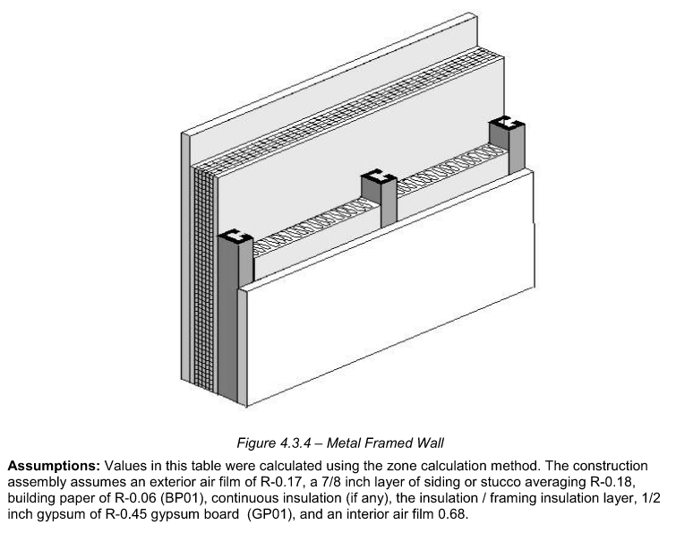
Exterior Walls
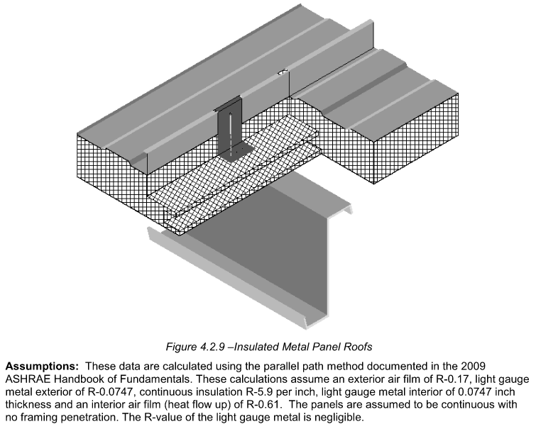
Exterior Roofs
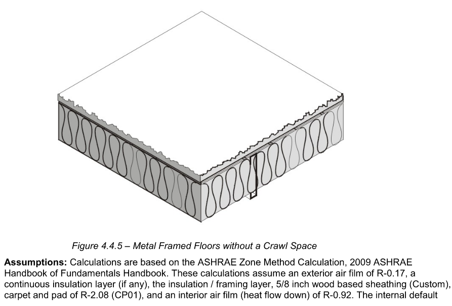
Exterior Floors
1.2 - Geometry
Non-Residential Building Geometry
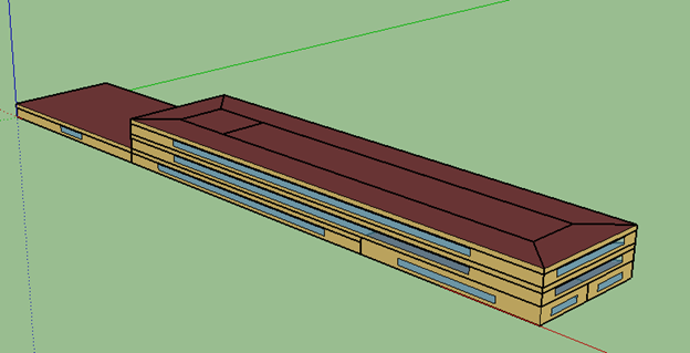
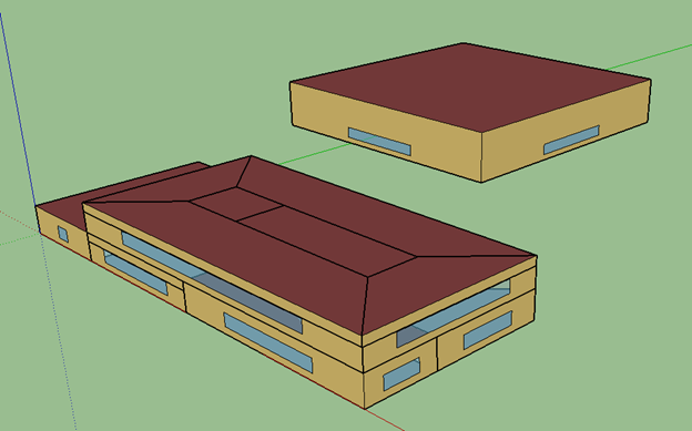
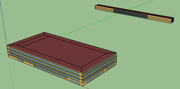
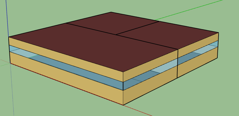
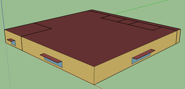
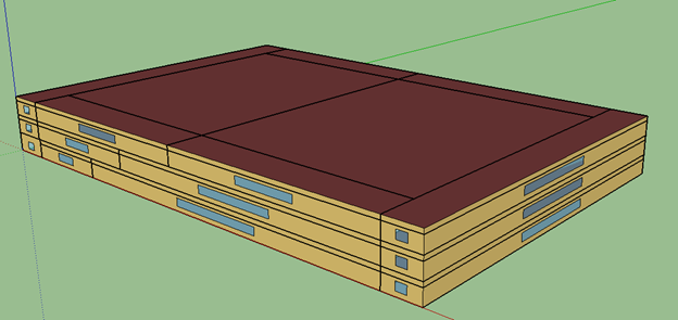
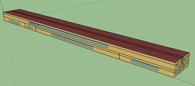
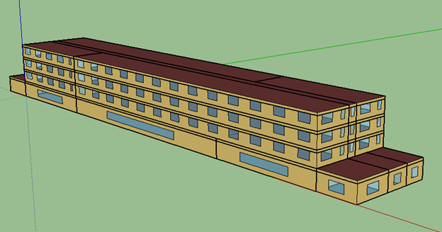
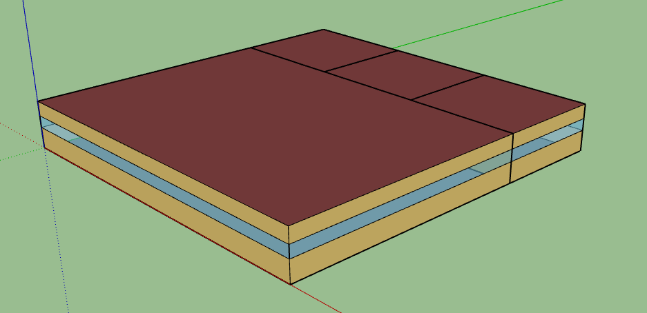
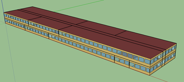
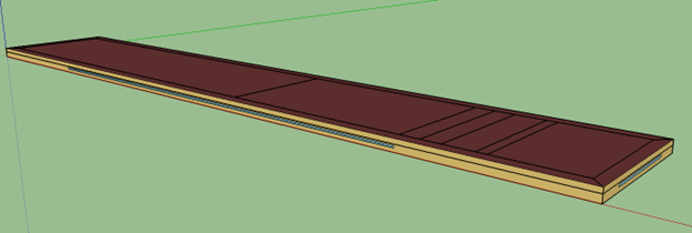
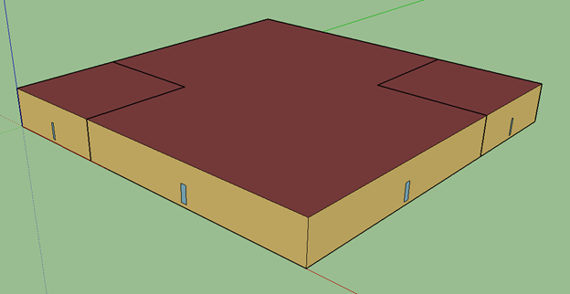
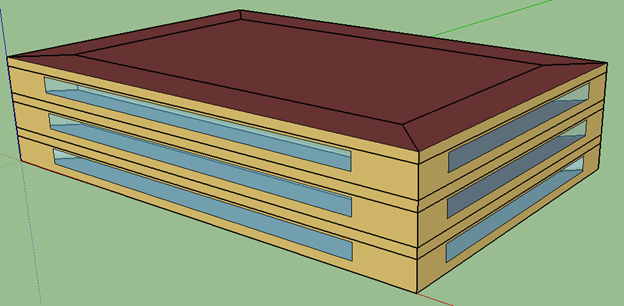
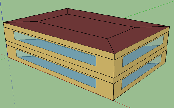
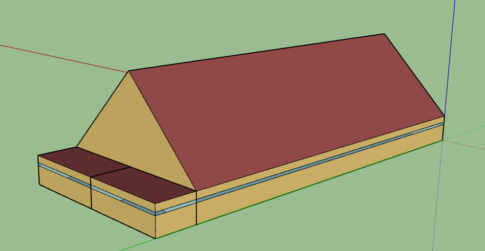
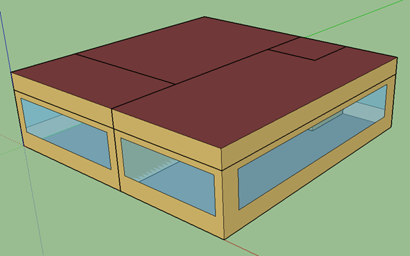
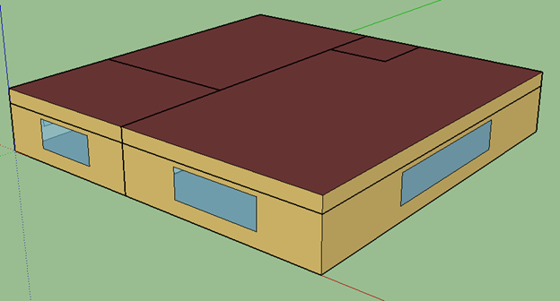
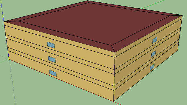
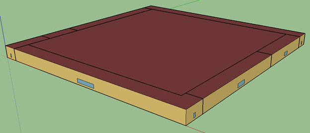
Building geometries for the non-residential DEER prototypes are sourced from NREL’s Building Component Library. The Create DEER Prototype Building Measure was used to generate building geometry files for the 22 non-residential DEER prototypes in EnergyPlus format.
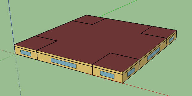
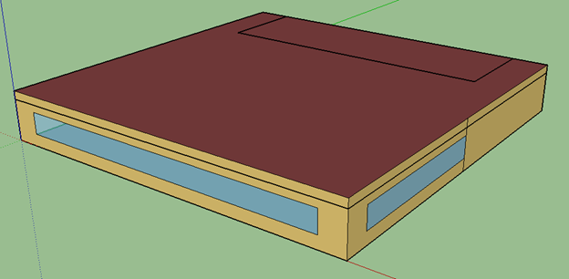
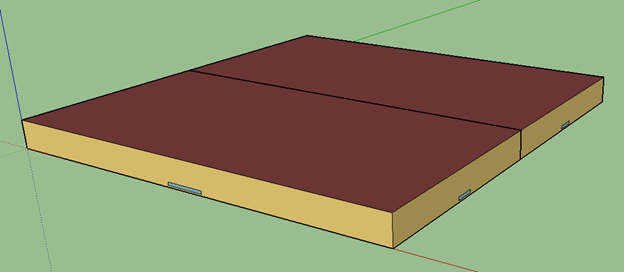
The geometries remained unchanged from the initial source files. The 3D model geometry can be viewed with either the Euclid or OpenStudio extensions in Sketchup. Screenshots of the 3D geometry for each of the non-residential DEER prototypes are shown below.
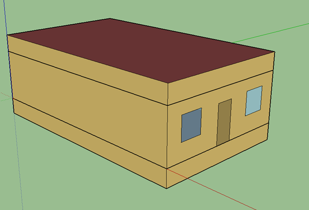
Geometries for the new non-residential prototype models (i.e. Fin, Lib, Rel), which are not included in the pre-existing DEER model set, were developed in EnergyPlus format as part of the CalBEM Benchmarking Database project. Representative geometry and space functions for the new building types are derived from data in the 2012 Commercial Buildings Energy Consumption Survey (CBECS). CBECS is a national sample survey that collects information on the US commercial buildings stock, including energy-related building characteristics and energy usage data. Variables included in the survey data such as building shape, building area, glazing percentage, primary space types, floor-to-ceiling height, and roof tilt were used to produce representative geometry for the three building types. Screenshots of the 3D geometry for each of the new commercial prototypes are shown below.
Assembly (Asm)
Education - Primary School (EPr)

Education - Relocatable Classroom (ERC)
Education - Secondary School (ESe)
Education - University (EUn)
Financial Institution (Fin)
Grocery (Gro)
Health/Medical - Hospital (Hsp)
Health/Medical - Nursing Home (Nrs)
Lodging - Hotel (Htl)
Library (Lib)
Lodging - Motel (Mtl)
Manufacturing - Biotech (MBT)
Manufacturing - Light Industrial (MLI)
Office - Large (OfL)
Office - Small (OfS)
Religious Facility (Rel)
Restaurant - Fast-Food (RFF)
Restaurant - Sit-Down (RSD)
Retail - Multistory Large (Rt3)
Retail - Single-Story Large (RtL)
Retail - Small (RtS)
Storage - Conditioned (SCn)
1.3 - HVAC
Non-Residential HVAC Assumptions
Airside HVAC
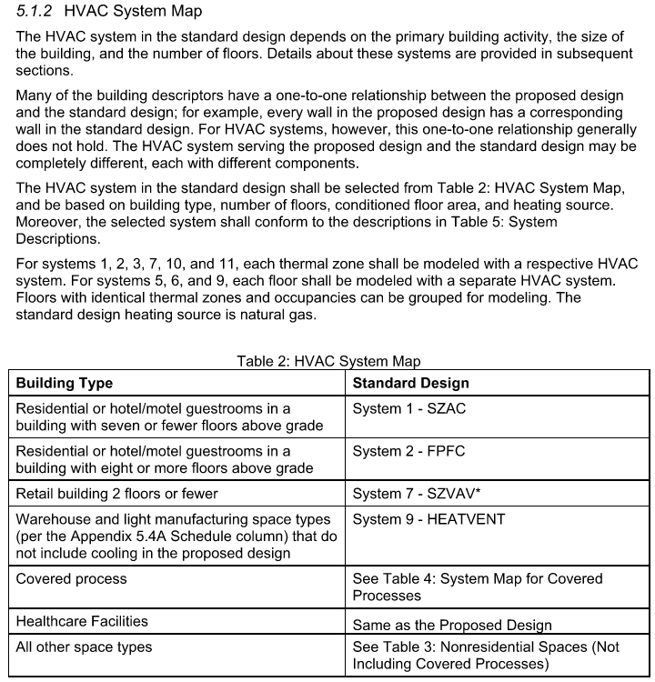
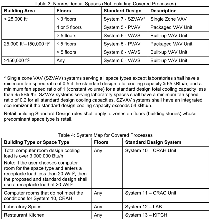
Airside HVAC system types are specified according to the HVAC System Map in the ACM Reference Manual (Table 2, below). The HVAC System map prescribes standard design system types based on the building type, building area, and number of floors. Other components of the building can also influence the HVAC type and/or required controls, including cooling capacity (e.g. economizers), occupant density (e.g. demand-controlled ventilation), and space type (e.g. kitchen, data centers, and labs). Equipment performance represents minimal compliance with the prescriptive requirements for each code vintage.
Waterside HVAC
Plant equipment is determined based on the airside system coil types and other building parameters. Airside systems with water heating coils are served by non-condensing boilers. The number of boilers serving the hot water loop is based solely on conditioned floor area, and is therefore consistent for each building type regardless of loads. Chiller type, condenser type, and quantity are dependent on the building’s peak cooling load, and therefore vary depending on climate zone and vintage.
The table below summarizes the HVAC systems serving each prototype building. Many of the prototypes are served by more than one HVAC system type, due to the variety of spaces and/or differences in thermal loads in a particular building. Chiller type and quantity are not indicated because they depend on the building’s peak cooling load, which varies by location.
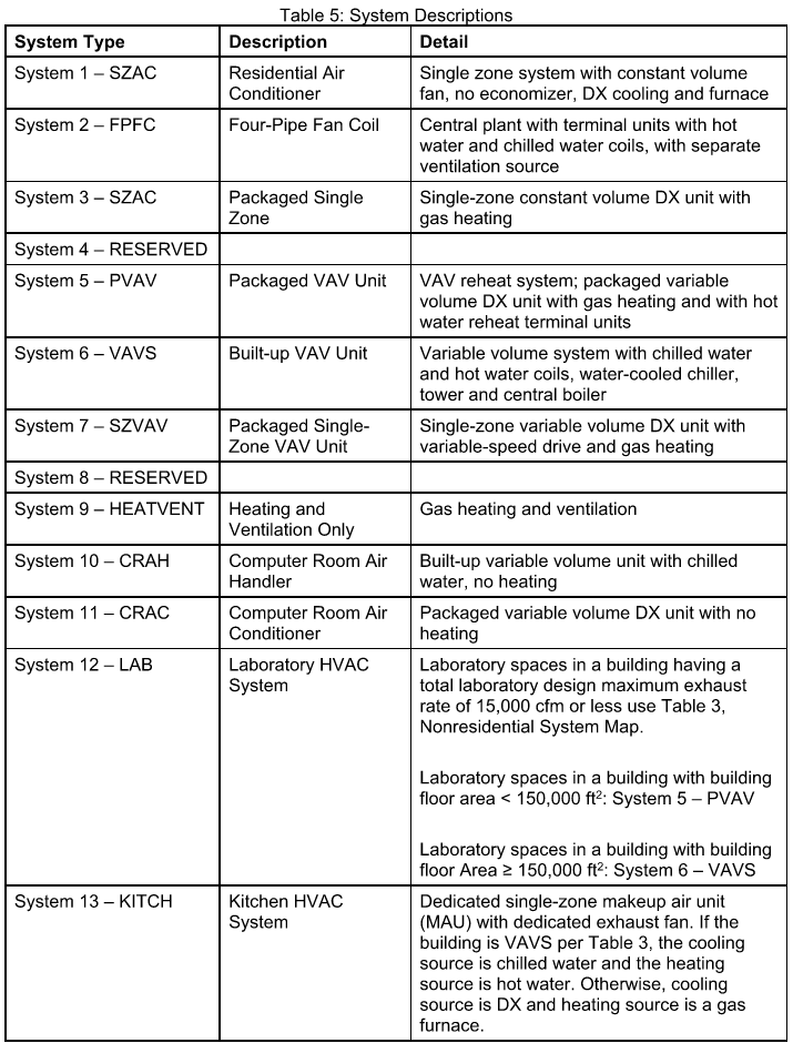
HVAC Systems
| Building | HVAC System 1 | HVAC System 2 | Kitchen System | Data Center System | Lab System | Heating Plant | Cooling Plant |
|---|
| Asm | Sys5-PVAV | NONE | NONE | NONE | NONE | 2 Boilers | NONE |
| ECC | Sys6-VAV | NONE | Sys13 | Sys11 | NONE | 2 Boilers | Chillers |
| Epr | Sys7-SZVAV-DCV | Sys7-SZCAV | Sys13 | NONE | NONE | NONE | NONE |
| ERC | Sys7-SZCAV | NONE | NONE | NONE | NONE | NONE | NONE |
| ESe | Sys5-PVAV-DCV | Sys7-SZVAV | Sys13 | Sys11 | NONE | 2 Boilers | NONE |
| Eun | Sys6-VAV-DCV | Sys1-SZAC | Sys13 | Sys11 | NONE | 2 Boilers | Chillers |
| Fin | Sys7-SZVAV | NONE | NONE | NONE | NONE | NONE | NONE |
| Gro | Sys7-SZVAV | Sys7-SZCAV | NONE | NONE | NONE | NONE | NONE |
| Hsp | Sys6-VAV-DCV | Sys6-VAV | Sys13 | NONE | NONE | 2 Boilers | Chillers |
| Htl | Sys5-PVAV | Sys1-SZAC | Sys13 | NONE | NONE | 2 Boilers | NONE |
| Lib | Sys7-SZVAV | NONE | NONE | NONE | NONE | NONE | NONE |
| MBT | Sys6-VAV-DCV | Sys6-VAV | Sys13 | Sys11 | Sys12A | 2 Boilers | Chillers |
| MLI | Sys5-PVAV | NONE | NONE | NONE | NONE | 2 Boilers | NONE |
| Mtl | Sys5-PVAV | Sys1-SZAC | NONE | NONE | NONE | 2 Boilers | NONE |
| Nrs | Sys5-PVAV-DCV | Sys5-PVAV | Sys13 | NONE | NONE | 2 Boilers | NONE |
| OfL | Sys6-VAV | Sys6-VAV-DCV | NONE | NONE | NONE | 2 Boilers | Chillers |
| OfS | Sys7-SZCAV | NONE | NONE | NONE | NONE | NONE | NONE |
| Rel | Sys7-SZVAV | NONE | NONE | NONE | NONE | NONE | NONE |
| RFF | Sys7-SZCAV | NONE | Sys13 | NONE | NONE | NONE | NONE |
| RSD | Sys7-SZCAV | Sys5-PVAV-DCV | Sys13 | NONE | NONE | NONE | NONE |
| Rt3 | Sys5-PVAV-DCV | Sys7-SZCAV | NONE | NONE | NONE | 2 Boilers | NONE |
| RtL | Sys7-SZVAV | Sys7-SZCAV | Sys13 | NONE | NONE | NONE | NONE |
| RtS | Sys7-SZVAV | Sys7-SZCAV | NONE | NONE | NONE | NONE | NONE |
| SCn | Sys6-VAV | NONE | NONE | NONE | NONE | 2 Boilers | Chillers |
HVAC System Map & Description - ACM Reference Manual
1.4 - Schedules
Non-residential schedules
Schedule Groups
Schedule groups are defined in ACM Reference Manual Appendix 5.4B. Each schedule group defines specific hourly profiles for thermostat setpoints, HVAC system availability, occupancy, lighting, equipment, and domestic hot water consumption.
Each space function has an associated schedule group, as listed in the ACM Appendix 5.4A. The ACM defines the following schedule groups:
- Assembly
- Data
- Health
- Laboratory
- Manufacturing
- Office
- Parking
- ResidentialCommon
- ResidentialLiving
- Restaurant
- Retail
- School
- Unoccupied
- Warehouse
Schedule Group Assignment
Schedule groups are assigned to thermal zones based on the zone’s space function and the HVAC system serving the zone. Where multiple zones are served by the same HVAC system, the schedule group associated with the predominant space function (by floor area) is assigned to all zones served by the system. For example, if office space accounts for 60 percent of a building floor, and all zones on that floor are served by the same HVAC system, then all thermal zones on that floor will be assigned the Office schedule group.
Schedule Variations
Three sets of schedules were developed for each schedule group:
The hourly schedules from Appendix 5.4B serve as the ‘average’ schedules for most of the schedule groups (except Warehouse and School). The average schedules are shortened by one hour and lengthened by one hour to generate the short and long schedules, respectively.
Modifications to ACM schedules
Schedules used in the database models are modified from those listed in Appendix 5.4B for two schedule groups: School and Warehouse.
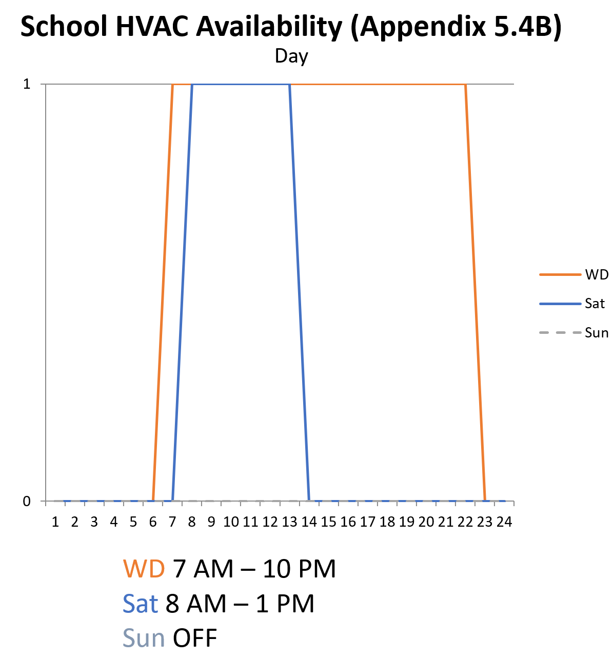
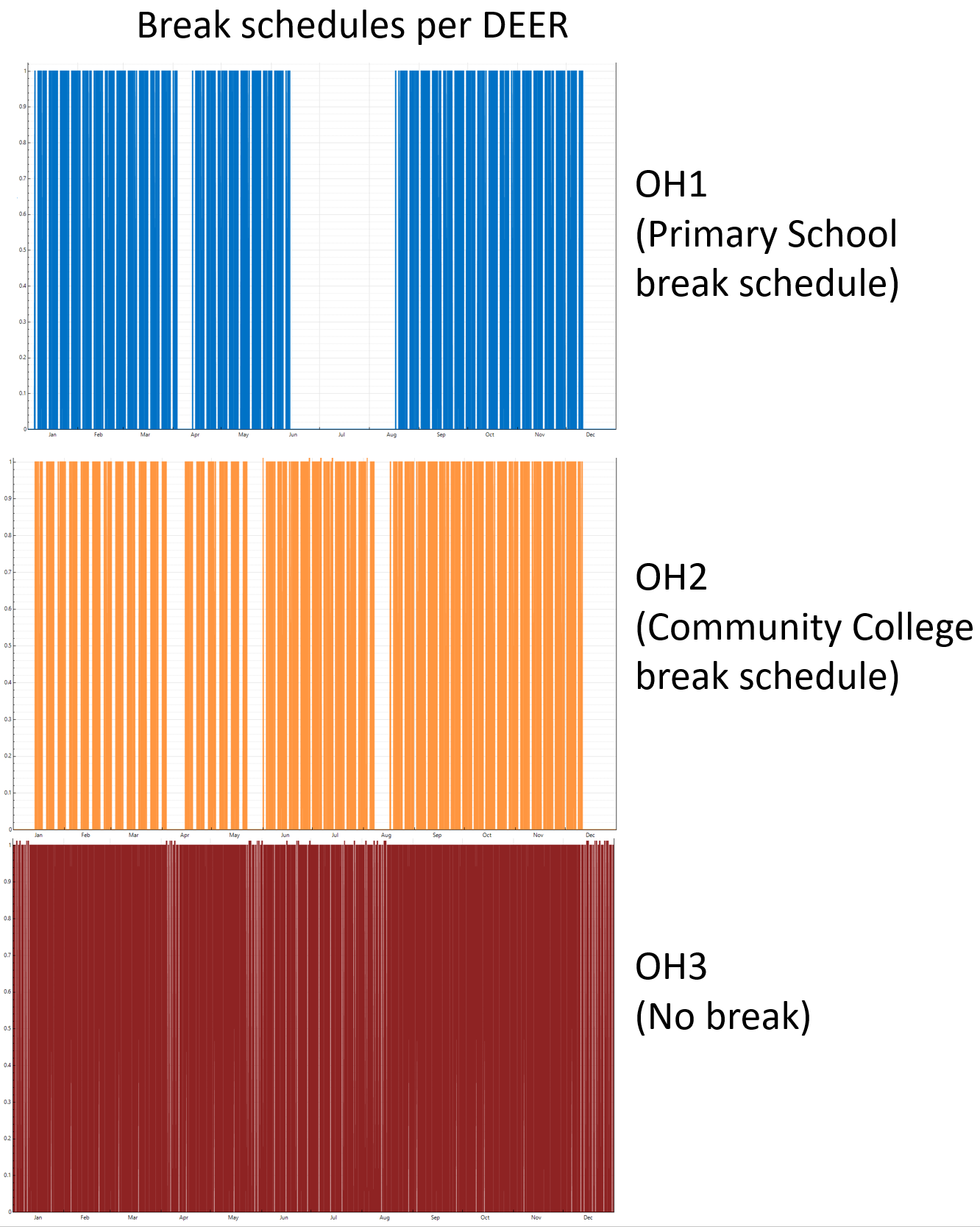
School Schedule Modifications
The School schedule group is modified from the original hourly profiles in Appendix 5.4B to represent typical primary school (short), community college (average), and university (long) schedules. The hourly/daily schedules are the same as Appendix 5.4B, however seasonal variations are incorporated to represent breaks for the three different school types.
School daily / hourly profile
School annual profile (HVAC on/off)
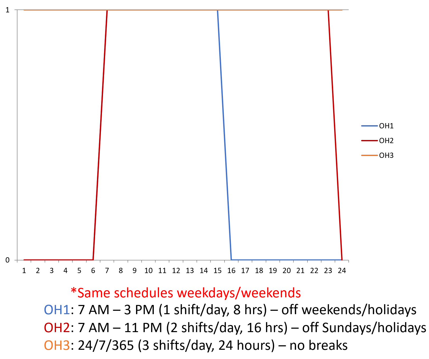
Warehouse Schedule Modifications
The Warehouse schedule group is modified from the original hourly profiles in Appendix 5.4B to represent one, two, and three shifts per day, corresponding to short (OH1), average (OH2), and long (OH3) schedules, respectively. The daily schedules remained consistent throughout the year.
Warehouse daily / hourly profile (HVAC on/off)
1.5 - Space Functions
Non-Residential space functions
Schedules characterizing the hourly profiles for thermostat setpoints, HVAC operation, and internal loads listed below are described in Schedules.
Each thermal zone in a building model is assigned a space function that characterizes design occupancy, ventilation, domestic hot water, exhaust, and internal load assumptions for the zone. Space functions are defined in ACM Reference Manual Appendix 5.4A.
Internal Loads
Design internal loads include:
- Lighting power density (W/ft2)
- Equipment power density (electric & gas) (W/ft2)
- Occupant density (People / 1000 ft2)
- Occupant sensible and latent heat gain (Watts per person)
Ventilation
Ventilation requirements include:
- Minimum ventilation per area for design sizing (CFM/ft2)
- Minimum ventilation per area for demand-controlled ventilation systems (CFM/ft2)
Exhaust
Exhaust requirements include:
- Minimum exhaust flow per area (CFM/ft2)
- Exhaust fan coupling with supply system fan (True/False)
Domestic Hot Water
Domestic hot water (DHW) assumptions include:
- DHW flow per zone area (GPM/ft2)
- Water heater fuel type (Electric or Natural Gas)
2 - Residential Models
Detailed descriptions and inputs for the non-residential BEM prototypes.
2.1 - Envelope
Residential envelope assumptions
Building envelope constructions and performance are sourced from the original DEER models, and are translated from DOE2 to CSE format. The MASControl database was used to generate inputs that vary envelope performance based on vintage and climate zones, and were applied accordingly to each prototype model.
2.2 - Geometry
Residential building geometry
Building geometries for the residential DEER prototypes are sourced from the original DEER models created in DOE2, and are translated from DOE2 to CSE format.
Modifications from DEER Geometry
The building geometry in the original DEER models varied the floor, wall, and window area by climate zone due to the extensive analysis that was conducted to generate the DEER models. For simplification, the floor, wall, and window area that was most common among the climate zones is used for all climate zones in the prototype models, and no shading objects are included.
Software to render CSE geometry in a visual format is not currently available.
2.3 - HVAC
Residential HVAC assumptions
Residental HVAC
All residential models have ducted central air conditioning and gas-fired furnace heating. The MASControl database was used togenerate inputs that vary HVAC performance parameters (i.e., fan power, heating and cooling efficiency) based on vintage and climate zones, and were applied accordingly to each prototype model. The HVAC systems operate all hours of the year, cycling on/off as needed to meet heating and cooling setpoints.
2.4 - Schedules
Residential schedules
Groups of schedules for occupancy, lighting, and plug loads were varied to represent short, average, and long schedules. The original DEER model schedules serve as the average schedules. The short and long schedules were created by shortening and lengthening the average internal load schedules by approximately three hours each day.The HVAC system and zone temperature setpoints are constant. Details on the operating schedule variations for each building are listed in the model specification reports.
2.5 - Space Functions
Residential space functions
Schedules characterizing the hourly profiles for thermostat setpoints, HVAC operation, and internal loads listed below are described in Schedules.
Residential internal loads are sourced from the original DEER models, but translated from DOE2 to CSE format. Internal load assumptions are listed in the model specification reports.
Internal Loads
Design internal loads include:
- Lighting power (Watts)
- Equipment power (receptacles, cooking, refrigeration, dish washing, clothes washing and drying) (Watts)
- Occupancy (people per zone)
Domestic Hot Water
Domestic hot water (DHW) assumptions include:
- DHW draw profiles for sinks, baths, showers, dish washing, and clothes washing